Aviation Week and Space Technology
In Partnership With
Boeing

 September 8, 1969
P. 67 (7 Pages)
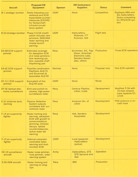
High-power traveling wave tube developed by Watkins-Johnson, can deliver 600 w. of continuous wave power throughout X-band for use in electronic countermeasures (ECM) systems. It can operate at 23% efficiency.
September 8, 1969
P. 67 (7 Pages)
High-power traveling wave tube developed by Watkins-Johnson, can deliver 600 w. of continuous wave power throughout X-band for use in electronic countermeasures (ECM) systems. It can operate at 23% efficiency.
 September 8, 1969
P. 67 (7 Pages)
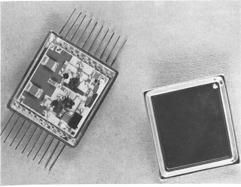
Typical subsystem or “supercomponent” made by Microwave Electronics of Teledyne for electronics countermeasures (ECM) repeater contains two traveling wave tubes, gain equalizers and power supply. Supercomponents are coming Into increasing use in ECM systems because they simplify interfacing and offer improved performance.
September 8, 1969
P. 67 (7 Pages)
Typical subsystem or “supercomponent” made by Microwave Electronics of Teledyne for electronics countermeasures (ECM) repeater contains two traveling wave tubes, gain equalizers and power supply. Supercomponents are coming Into increasing use in ECM systems because they simplify interfacing and offer improved performance.
 February 7, 1966
P. 48 (6 Pages)
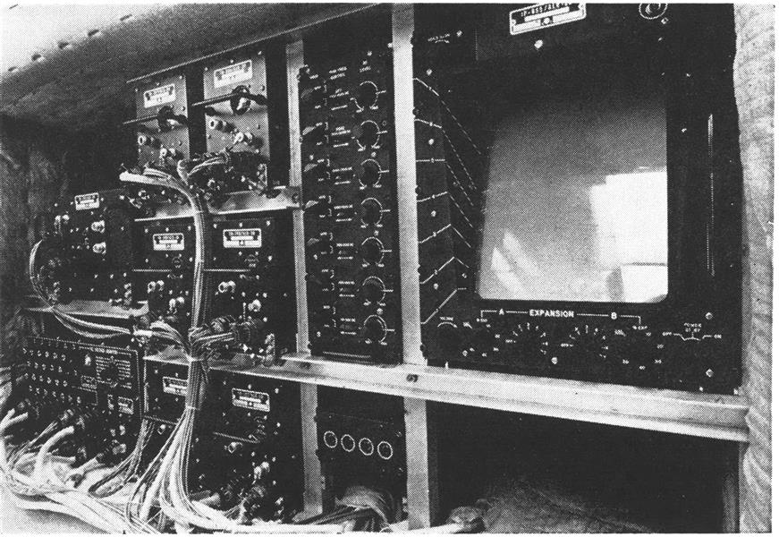
Installation of ALR-20 electronic countermeasures (ECM) receiver, shown in its entirety is expected to improve the ability of Strategic Air Command’s B-52 bomber crews to detect and counter hostile radar threats. Frequency, signal strength, signal modulation characteristics and relative indication of pulse repetition rates of threatening radars can be determined from ninetrace indicator display at right by the aircraft’s electronic warfare officer. The ALR-20 recently was flight tested by the Air Force in a B-52 at Eglin AFB.
February 7, 1966
P. 48 (6 Pages)
Installation of ALR-20 electronic countermeasures (ECM) receiver, shown in its entirety is expected to improve the ability of Strategic Air Command’s B-52 bomber crews to detect and counter hostile radar threats. Frequency, signal strength, signal modulation characteristics and relative indication of pulse repetition rates of threatening radars can be determined from ninetrace indicator display at right by the aircraft’s electronic warfare officer. The ALR-20 recently was flight tested by the Air Force in a B-52 at Eglin AFB.
 February 8, 1971
P. 18, 19
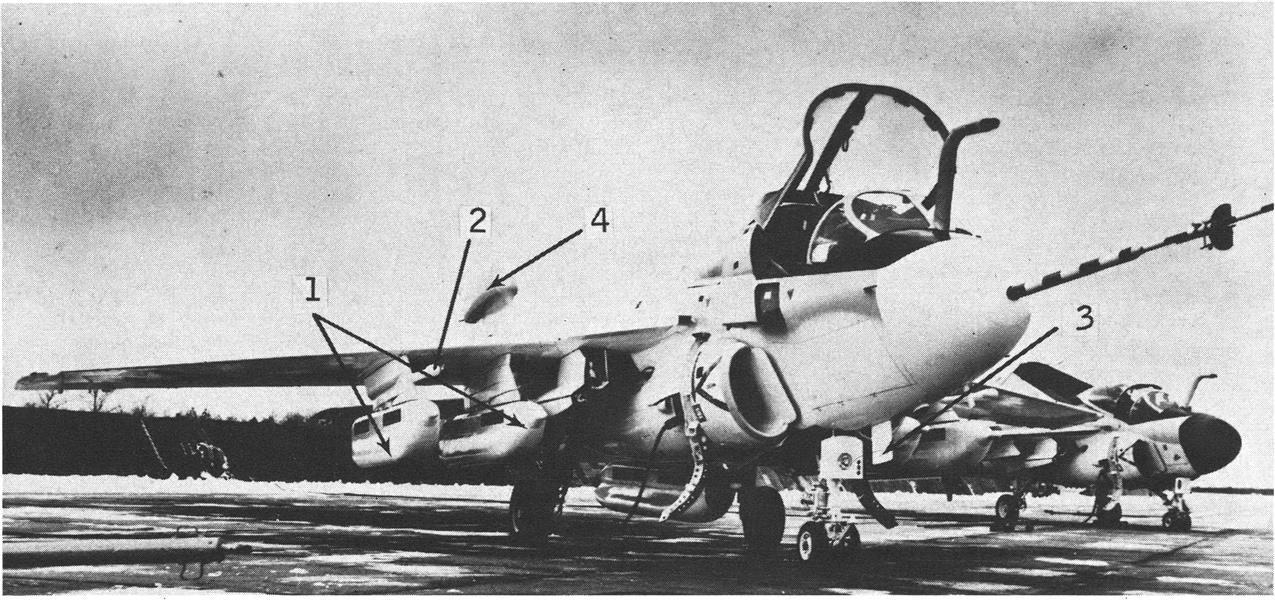
Visible features of electronic countermeasures (ECM) capability of Navy/Grumman EA-6B include tactical jamming system pods (1), antennas for internally-located deception ECM system (2), blade antenna for communications jamming system (3) and tail dome housing integration receivers and antennas (4).
February 8, 1971
P. 18, 19
Visible features of electronic countermeasures (ECM) capability of Navy/Grumman EA-6B include tactical jamming system pods (1), antennas for internally-located deception ECM system (2), blade antenna for communications jamming system (3) and tail dome housing integration receivers and antennas (4).
 February 21, 1972
P. 74
February 21, 1972
P. 74
 September 8, 1969
P. 67 (7 Pages)
for airborne internal or pod mounting, can provide high peak and continuous wave power in S-band for electric countermeasures applications. Developed by Warnecke Electron Tubes, Inc., a Northrop Corp. affiliate, the 18-lb. tube delivers 1 kw. in the continuous wave mode.
September 8, 1969
P. 67 (7 Pages)
for airborne internal or pod mounting, can provide high peak and continuous wave power in S-band for electric countermeasures applications. Developed by Warnecke Electron Tubes, Inc., a Northrop Corp. affiliate, the 18-lb. tube delivers 1 kw. in the continuous wave mode.
 September 8, 1969
P. 67 (7 Pages)
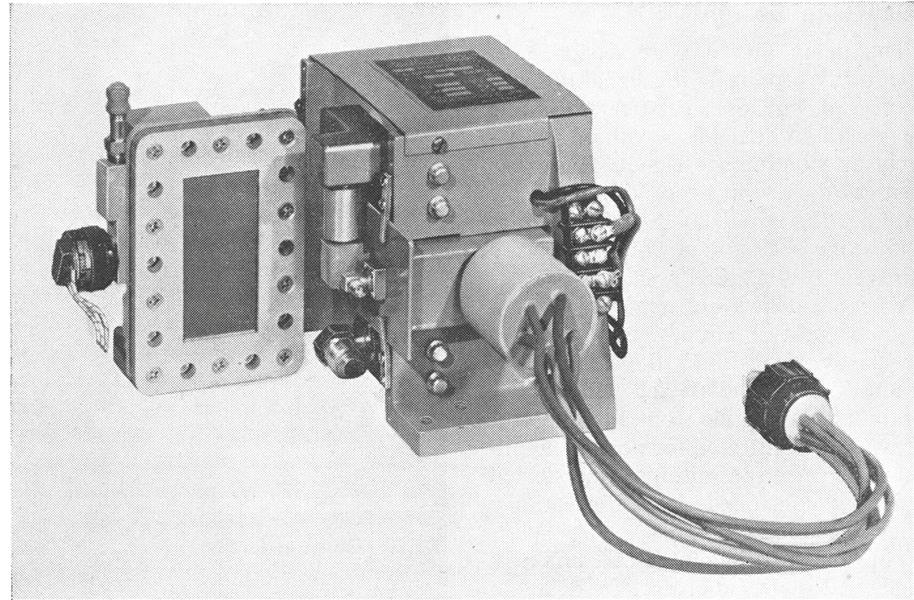
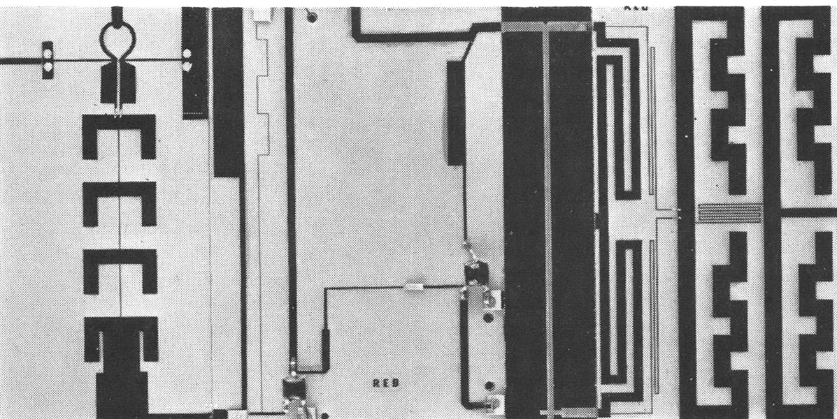
Intermediate frequency output (60 me.) for fire control radar receiver was developed by Microwave Associates, Burlington, Mass. Microcircuit contains X-band balanced mixer at L-band amplifier and L-band balanced mixer all mounted on VA x 2-in. substrate area. Wideband radio frequency amplifier
September 8, 1969
P. 67 (7 Pages)
Intermediate frequency output (60 me.) for fire control radar receiver was developed by Microwave Associates, Burlington, Mass. Microcircuit contains X-band balanced mixer at L-band amplifier and L-band balanced mixer all mounted on VA x 2-in. substrate area. Wideband radio frequency amplifier
 September 8, 1969
P. 67 (7 Pages)
which has 40 db. gain in the 1-60 me. range, is sample of thick film microcircuits being developed by Applied Technology Div. of Itek Corp. for application in company’s future reconnaissance and ECM systems. Company also is at work on wideband amplifiers covering the 30-100 me. and 100-500 me. range and precision tracking digital/analog networks.
September 8, 1969
P. 67 (7 Pages)
which has 40 db. gain in the 1-60 me. range, is sample of thick film microcircuits being developed by Applied Technology Div. of Itek Corp. for application in company’s future reconnaissance and ECM systems. Company also is at work on wideband amplifiers covering the 30-100 me. and 100-500 me. range and precision tracking digital/analog networks.
 September 8, 1969
P. 67 (7 Pages)
Test vehicle for dualmode traveling wave tube is being developed by Hughes Aircraft Co. Dualmode tube offers possibility of being able to operate in either continuous wave or pulsed modes from single main power supply to enhance flexibility of ECM jammer.
September 8, 1969
P. 67 (7 Pages)
Test vehicle for dualmode traveling wave tube is being developed by Hughes Aircraft Co. Dualmode tube offers possibility of being able to operate in either continuous wave or pulsed modes from single main power supply to enhance flexibility of ECM jammer.
 February 21, 1972
P. 101 (3 Pages)
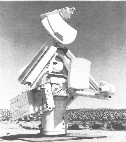
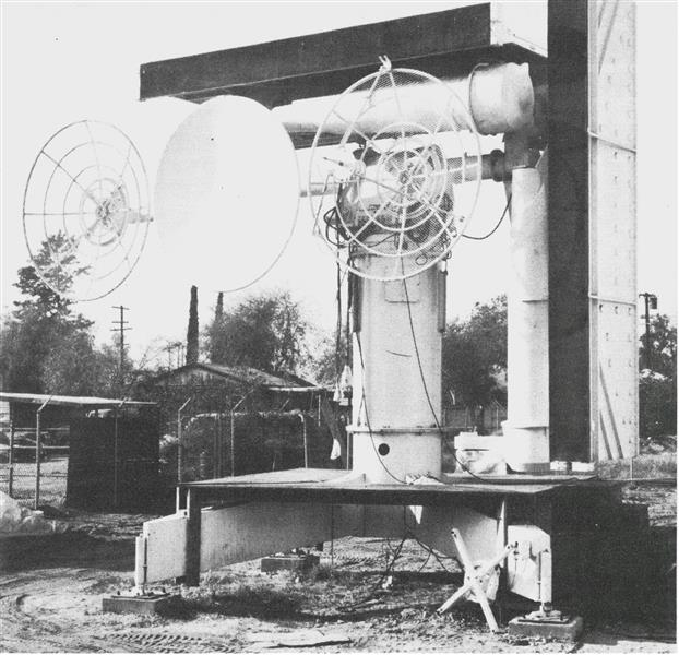
Navy simulation of Soviet SA-3 Low Blow radar at Naval Weapons Center duplicates electrical performance of the tracking/guidance radar for the Soviet low-altitude missile. Mimic Low Blow also closely resembles its Soviet counterpart with scanning antennas at right angles to one another and at 45 deg. to the ground plane. Two clipped parabolic sections, one at top, presumably for transmitting guidance signals, the other beneath it, for transmitting tracking
February 21, 1972
P. 101 (3 Pages)
Navy simulation of Soviet SA-3 Low Blow radar at Naval Weapons Center duplicates electrical performance of the tracking/guidance radar for the Soviet low-altitude missile. Mimic Low Blow also closely resembles its Soviet counterpart with scanning antennas at right angles to one another and at 45 deg. to the ground plane. Two clipped parabolic sections, one at top, presumably for transmitting guidance signals, the other beneath it, for transmitting tracking
 July 10, 1961
P. 71, 69
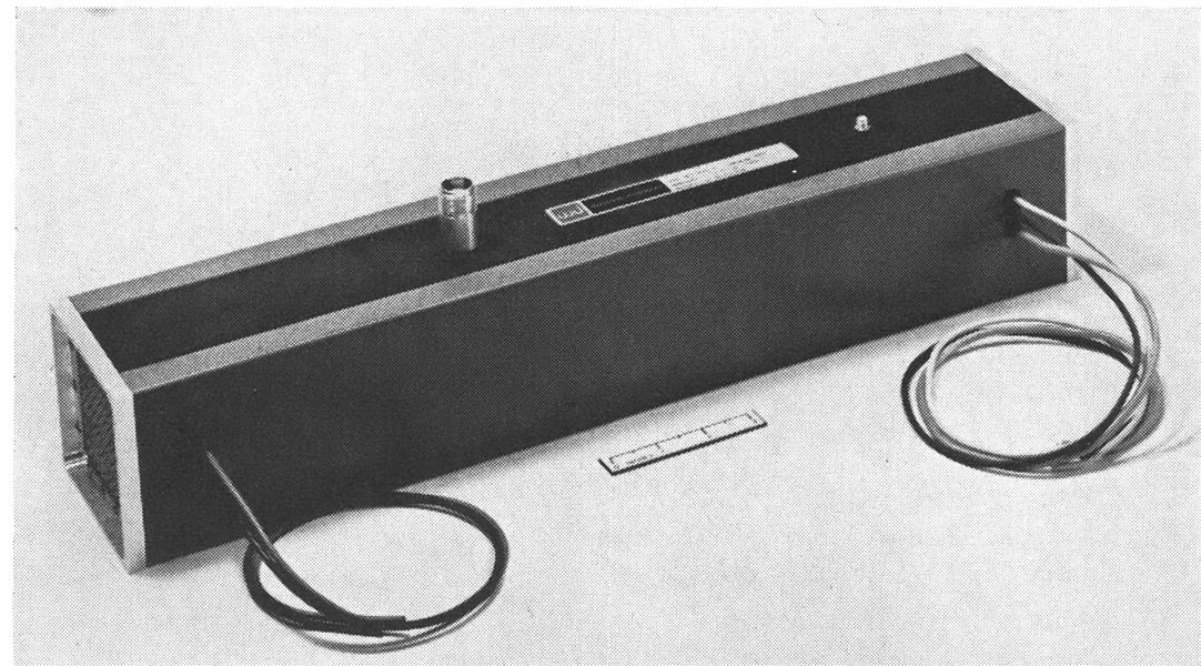
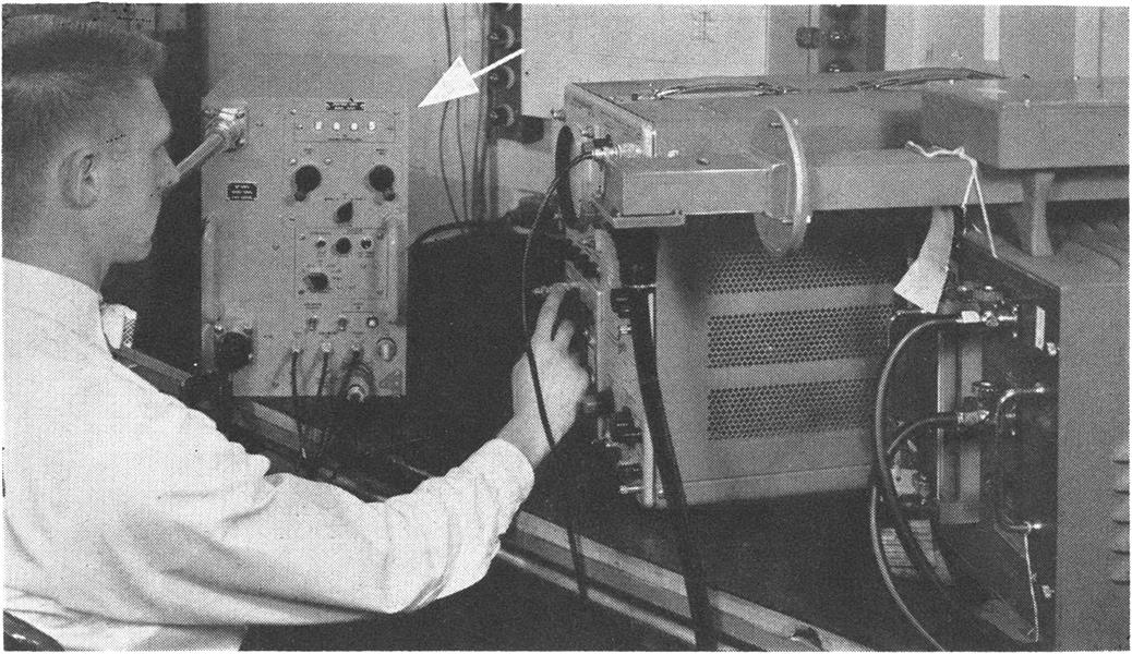
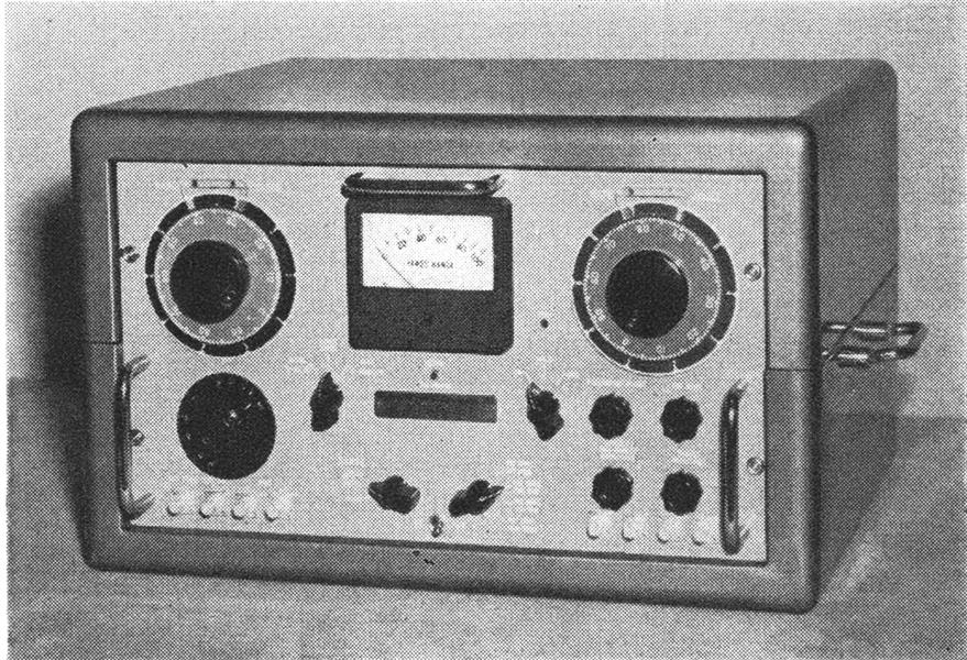
INCREMENTAL power spectrum analyzer (arrow), developed by Hallicrafters for testing ECM equipment and microwave tubes, provides continuous display of average power levels in 10-mc. increments over a band of 1,250 me. at S-band, with high accuracy.
July 10, 1961
P. 71, 69
INCREMENTAL power spectrum analyzer (arrow), developed by Hallicrafters for testing ECM equipment and microwave tubes, provides continuous display of average power levels in 10-mc. increments over a band of 1,250 me. at S-band, with high accuracy.
 May 11, 1959
P. 104 (3 Pages)
May 11, 1959
P. 104 (3 Pages)
 September 8, 1969
P. 67 (7 Pages)
Small spiral antennas, developed by TRW Systems Group, can obtain precise bearing data for electronic intelligence systems. They can be flush mounted in fuselage.
September 8, 1969
P. 67 (7 Pages)
Small spiral antennas, developed by TRW Systems Group, can obtain precise bearing data for electronic intelligence systems. They can be flush mounted in fuselage.
 May 11, 1959
P. 104 (3 Pages)
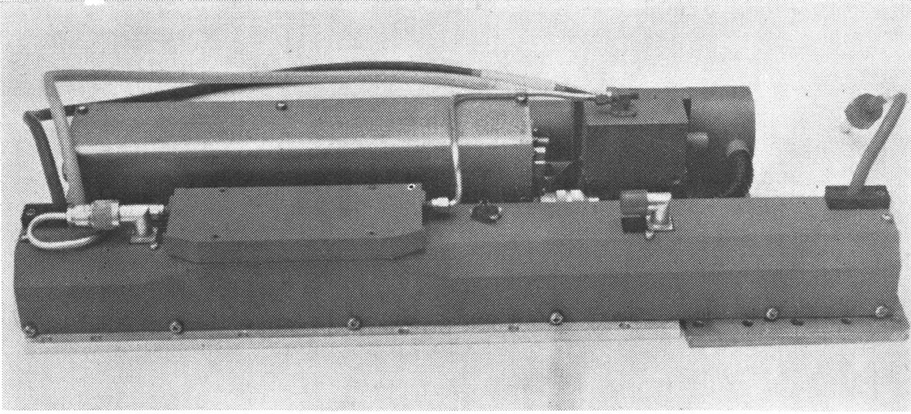
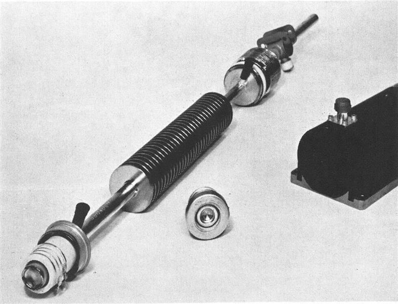
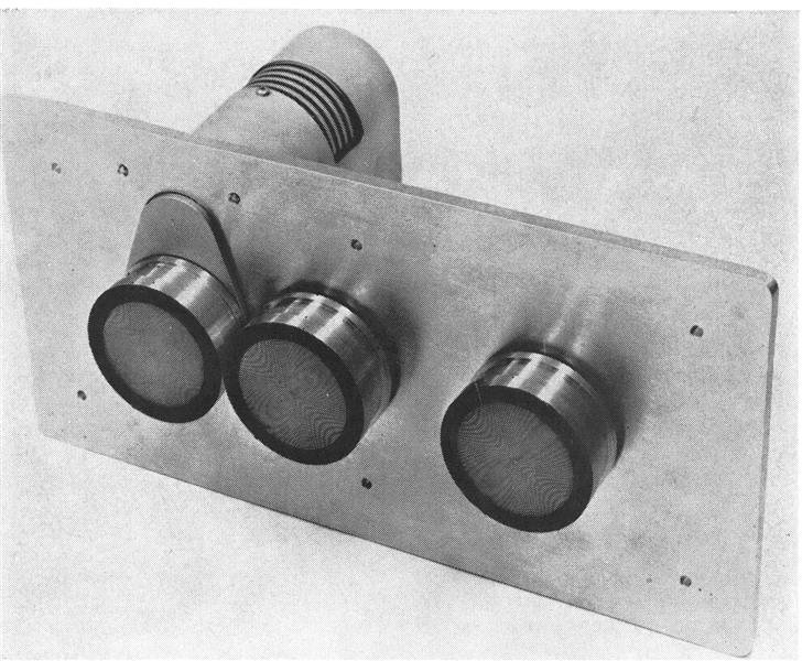
CLOSEUP of two ECM simulators shows Model 313 radar analyzer/calibrator (left) and companion Model 413 azimuth/elevator unit (right) which simulates moving targets.
May 11, 1959
P. 104 (3 Pages)
CLOSEUP of two ECM simulators shows Model 313 radar analyzer/calibrator (left) and companion Model 413 azimuth/elevator unit (right) which simulates moving targets.
 July 10, 1961
P. 71, 69
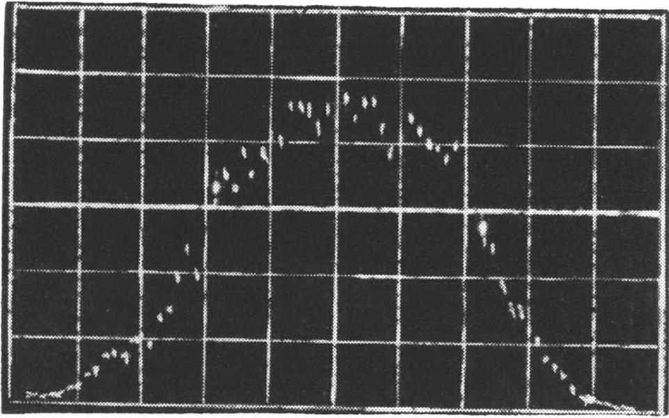
DISPLAY is of average power vs. frequency obtained by use of new spectrum analyzer. It was created by FM noise modulation of a voltage-tunable magnetron.
July 10, 1961
P. 71, 69
DISPLAY is of average power vs. frequency obtained by use of new spectrum analyzer. It was created by FM noise modulation of a voltage-tunable magnetron.
 February 21, 1972
P. 101 (3 Pages)
Fan Song E mimic radar being modified for Air Force by Guide Scientific Industries resembles Soviet model, except for the location of the parabolic dishes. The radar set simulates performance of the Russian model for pilot training.
February 21, 1972
P. 101 (3 Pages)
Fan Song E mimic radar being modified for Air Force by Guide Scientific Industries resembles Soviet model, except for the location of the parabolic dishes. The radar set simulates performance of the Russian model for pilot training.
 March 4, 1968
P. 18, 19
AC-130 Gunship Tests Completed
March 4, 1968
P. 18, 19
AC-130 Gunship Tests Completed
 September 8, 1969
P. 67 (7 Pages)
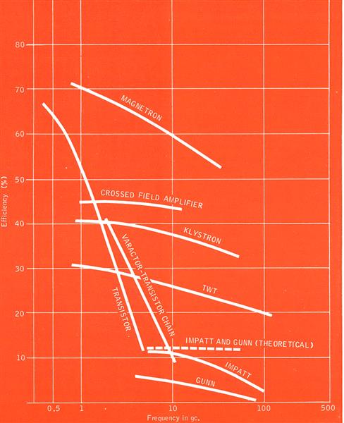
Efficiency curves of various microwave active devices indicate that transistor is the only solid-state device that can match conventional microwave signal sources and amplifiers—and then only at lower frequencies. Curves were prepared by Allan Scott of Varian Associates. Injected-beam, crossed-field amplifier
September 8, 1969
P. 67 (7 Pages)
Efficiency curves of various microwave active devices indicate that transistor is the only solid-state device that can match conventional microwave signal sources and amplifiers—and then only at lower frequencies. Curves were prepared by Allan Scott of Varian Associates. Injected-beam, crossed-field amplifier
 November 18, 1974
P. 58
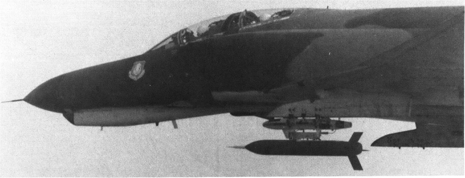
Celesco Propelled Decoy mounted beneath a McDonnell Douglas F-4 and seen silhouetted against background is designed to perform electronic warfare missions as an aid to tactical aircraft. The decoy can carry active and passive ECM payloads. It has wings that snap open on command after separation from the aircraft and a cruciform-shaped tail structure.
November 18, 1974
P. 58
Celesco Propelled Decoy mounted beneath a McDonnell Douglas F-4 and seen silhouetted against background is designed to perform electronic warfare missions as an aid to tactical aircraft. The decoy can carry active and passive ECM payloads. It has wings that snap open on command after separation from the aircraft and a cruciform-shaped tail structure.
 February 21, 1972
P. 101 (3 Pages)
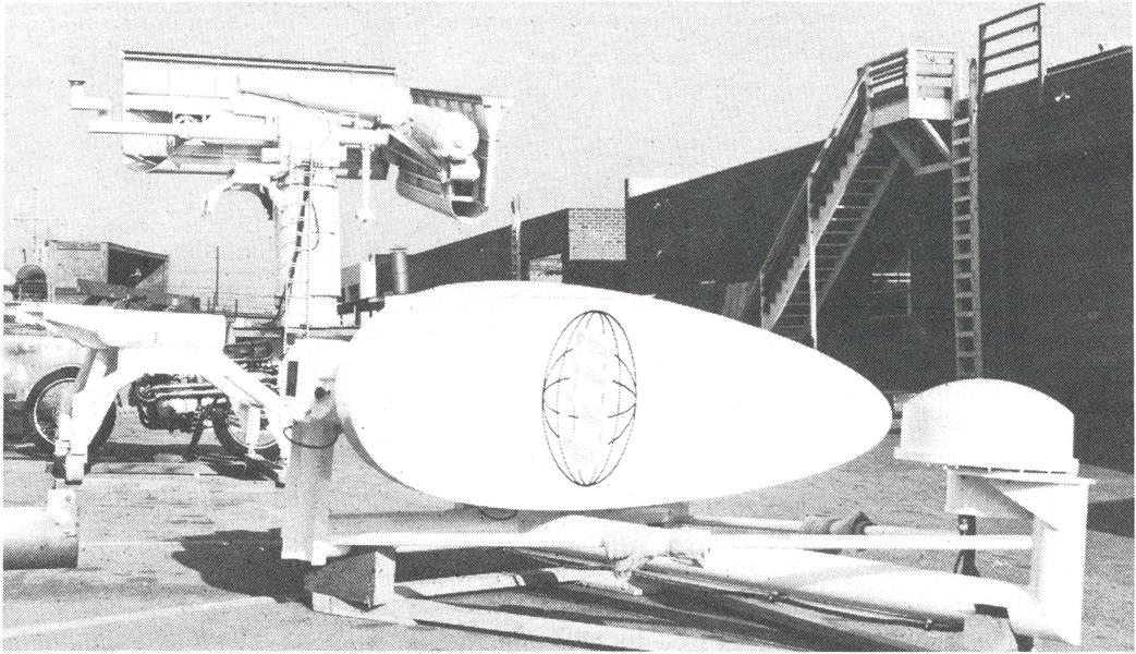
Orange-peel shaped parabolic dish with a special rotating scanner at its focus is designed presumably for use in a Navy simulator of Soviet Peel Group radar which directs naval versions of the SA-3 Goa missile. In background is a Fan Song SA-2 Guideline radar simulator being modified by Guide Scientific Industries for the Air Force.
February 21, 1972
P. 101 (3 Pages)
Orange-peel shaped parabolic dish with a special rotating scanner at its focus is designed presumably for use in a Navy simulator of Soviet Peel Group radar which directs naval versions of the SA-3 Goa missile. In background is a Fan Song SA-2 Guideline radar simulator being modified by Guide Scientific Industries for the Air Force.